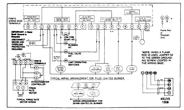
power flame burner wiring diagram
Reset and determine cause for apparent flame failure. Wiring diagram fxe 1975 earliest.
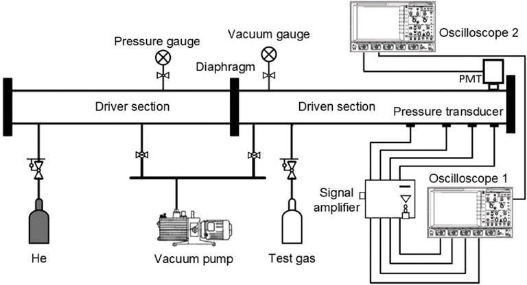
Frontiers Experimental And Numerical Studies Of Ignition Delay Time And Laminar Flame Speed Of Jp 10 At Elevated Temperature Conditions
Power Flame Field Service is an important part of keeping your burner operating reliably and successfully all year.
. We manufacture a wide range of commercial burners industrial burners boiler burners. Comprehensive wiring diagrams are furnished with each burner. FD FDM Installation Operation Manual - POWER FLAME INCORPORATED 6 2.
OR_6319 Power Flame Burner Wiring Diagram Wiring Diagram Tips for Detecting Problems. Atwood Furnace Wiring Diagram. Packaged Liquid Waste Fuel Burning systems employing the basic design.
Power Flames team of service professionals works on numerous burners. If supplied 62 Electrical. Type C Burners are designed to fire a wide range of gaseous as well as 2 or similar distillate fuels.
General 211 Before beginning installation carefully study these. INSTALLATION 21 Burner Mounting. Tighten all terminal screws and consult.
61 Refer to wiring diagram shipped with burner and typical wiring diagrams Figures 5 and 5A. Loose connections or faulty wiring. 14 Pics about Diagram together with GM HEI Ignition Module Wiring Diagram.
6 WIRING 61 Refer to wiring diagram shipped with burner. 62Electrical installation must be made in accordance with the NEC NFPA 70 or Canadian Electrical Code Part 1 and applicable. Special panels for wall mounting or free standing.
Power flame wiring diagram Diagram together with GM HEI Ignition Module Wiring Diagram. Panels and burners are fire tested before shipment. If supplied 62 Electrical installation must be made in accordance with National Electrical Code and applicable local codes.
61 Refer to wiring diagram shipped with burner and typical wiring diagrams Figures 5 and 5A. The two power leads black and white are located inside the burner panel. Click here for the Power Flame library.
61 Refer to wiring diagram shipped with burner and typical wiring diagrams Figures 5 and 5A. Reference the Power Flame VECTOR wiring diagram and ensure that all external control and interlock terminations are as depicted and that any interconnections resulting from remote. Flame safeguard control safety switch tripped out.
The two power leads black and white are located inside the burner panel. Flame safeguard control safety switch tripped out. The two power leads black and white are located inside the burner panel.
WIRING 61 Refer to wiring diagram shipped with burner.
Power Flame Commercial Industrial Burners Ati Of Ny
Suggested Wiring Diagram For Fireye Ep260 Ep261 Ep270 Programmer Logic

Wiring Diagrams Royal Series Royal Range Of California

Bell Sound 2154a Power Amplifier Schematic Electronic Service Manuals

Qbk Full Contrive Burnercontrol

Honeywell Ra116a Protectorelay Oil Burner Controls Installation Guide Manuals

Flame Detector Circuit

Power Flame Cici Boiler Rooms
Bunton Bobcat Ryan 930000 Power Unit 14 Hp Kohler Gear Drive Parts Diagram For Kohler Wire Harness

Furnace Power Flame Incorporated Oil Burner Gas Burner Circuit Board Graphics Schematic Combustion Png Pngegg

Energy Management Of Renewable Energy Based Combined Heat And Power Systems A Review Sciencedirect
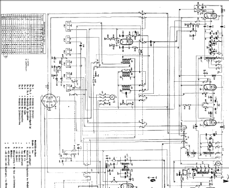
15 Watt Sender Empfanger 15 24b 124 Mil Trx Militar Verschiedene

Burner Control Units Bcu 460 Bcu 465 En

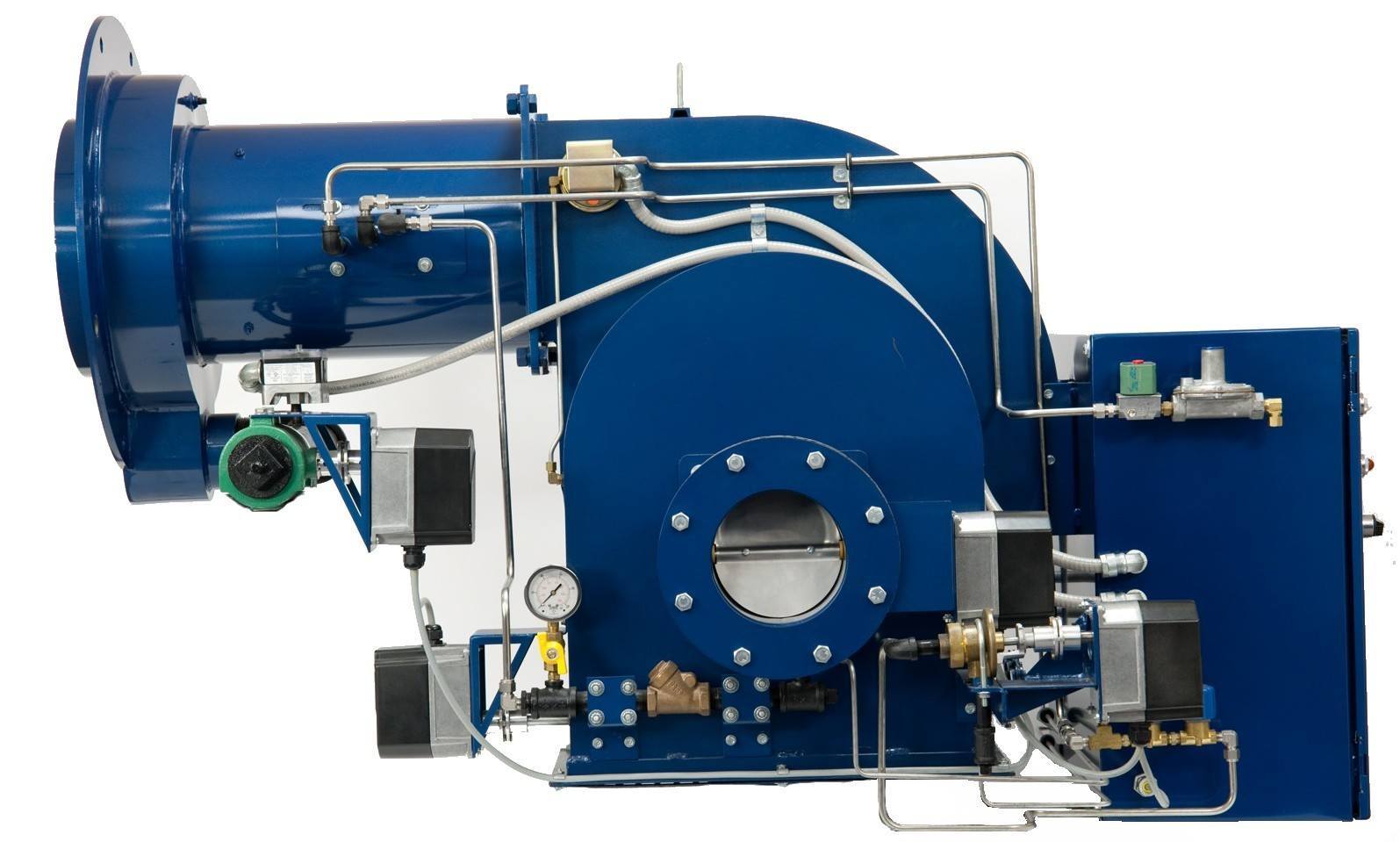
Power Flame

Power Flame
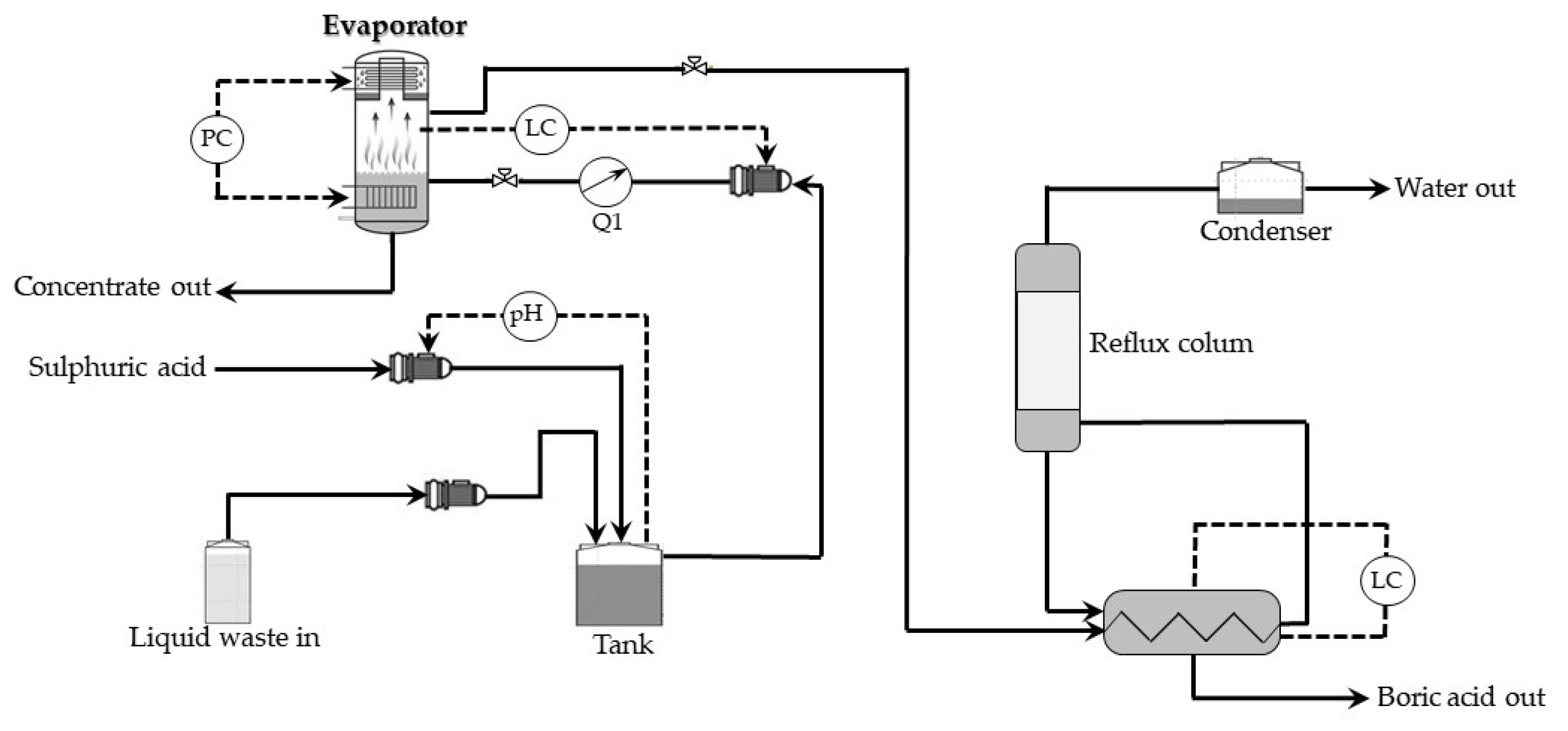
Energies Free Full Text Methods Of Thermal Treatment Of Radioactive Waste Html
![]()
Fireye Flame Safeguard And Combustion Controls